Need Help? Call Support at 1-888-769-8977 – Open Mon–Fri 6am to 3pm (Pacific Time)
Using Terminal Connections
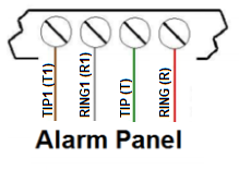
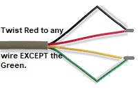
1. Open the alarm control panel and locate the Tip & Ring terminals on your alarm terminals. In most cases there will be both a T & T1 and a R & R1 terminal next to each other. Once located, remove any wiring you may have on ALL (4) terminals. (Note: Once disconnected, if you have a working phone line in the premises, lift a telephone-handset off-hook to check if you still have dial tone. If YOU STILL DO have dial tone, continue. If you NOW DO NOT have dial tone, twist the RED wire with any wire other than GREEN. Then Twist the GREEN and the remaining wire together. Your dial tone should have been restored. (If not, contact support.)
2. Using the BLACK MODULAR/WIRE PHONE CORD PROVIDED, connect the following wires to your alarm panel terminals:
-
RED to “T” / TIP of the alarm panel
-
GREEN to “R” / RING of the alarm panel.
-
BLUE to a POSITIVE “+” power terminal.
-
PURPLE to a NEGATIVE “-” GROUND terminal.
-
BLACK & YELLOW to Key Control. (Connect ONLY if adding remote arm/disarm.) This is a dry contact pair up to the user (you) to determine the control panel compatibility & connection points.
3. Now connect the MODULAR SIDE of the BLACK cord you just connected to your Alarm Control Panel into the RED MARKED JACK. (Marked Alarm.) The LED’s will begin to illuminate.
NOTE: The IP-Alarm is shipped pre-configured for Ethernet Connectivity.
To switch to Wi-Fi -> CLICK HERE NOW
Or continue to #4 below to stay in Ethernet Connectivity mode.
4. Connect the BLUE MARKED JACK (Marked WAN) on the IP-Alarm directly to your local ROUTER or SWITCH musing a LAN or PATCH CORD. (Not provided.) Now plug the Allow five minutes for the IP-Alarm to connect to our servers and stabilize. The Following LEDS’ should be illuminated, with the exception of the WHITE LED.
-
RED LED = Power is ON.
-
YELLOW LED = ETHERNET connectivity is detected.
-
BLUE LED #1 & #2 = WI-FI is detected, but not connected in Ethernet mode.
-
GREEN LED = Device is CONNECTED to our server.
-
WHITE = ILLUMINATES only if the alarm control panel is “off-hook” and attempting to send signals.
If all is good, Let’s Test your alarm into the Monitoring Center.
-
(a) Prepare your alarm system for arming by closing all doors and windows.
-
(b) Proceed to arm your alarm system and allow it to go through its arming period, usually 90 seconds.
-
(c) Once fully armed, open an instant alarm area such as a window causing a full alarm condition and not just a pre-alarm condition. Note: The alarm siren or bell will begin to sound if in full alarm.
-
(c) Since your alarm may have time delays before transmitting an event, allow the alarm to stay in full alarm condition for 90 seconds. (You should also see the WHITE LED flash, indicating the alarm control panel is sending signals to out IP-Alarm. Then turn off your alarm system.
-
(d) Wait five minutes and repeat step (c) again.
-
(e) Call the 24-hour monitoring center at 1-800-765.2580 and provide them with your alarm account number and password.
-
(f) Verify with the Live Operator that alarm signals were received from your alarm system.
-
(g) Once you have verified alarm signals, please complete the form below:
-
Fill out my online form.