How to Determine Your Alarm Account Number: In most cases, you should have received a small piece of paper in the shipment of your transmitter with a “QR” code on one side and the 8-Digit alarm account number written on the other side. If you did not locate the account number this way, then using the pre-fix code of “M2UL” followed by the last-4 digits of the MAC address of your device, (ie. E2A7) you can determine the 8-digit alarm account number is M2ULE2A7.
UL FIRE Cellular & IP Transmitter Installation Guide
-
Step by step instructions to switch your Fire Alarm Monitoring using a MQ03-LTE-M-FIRE.
-
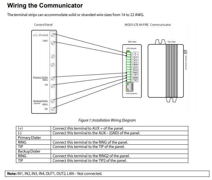
This Cellular/IP communicator connects to the Fire Alarm Panels (FAP) Positive + and Negative – outputs as well as to the Telco Tip and Ring DTMF dialer outputs for Line #1 and Line #2.
-
The device should be installed inside the Fire Alarm Panel (FAP) to meet NFPA 72 and for security purposes. Only the antenna should be on the outside of the Control Panel, secured using it’s magnetic base.
(1) Unpack the Device. It will have already have been fully programmed and ready for installation. Once installed, it should be in fully working condition, sending alarm signals to the monitoring center.
(2) Locate and then open your Fire Alarm Panel (FAP) (Not the arm/disarm keypad on the wall)
(3) Locate a positive + DC power source from the FAP that is from 12 to 29 volts. Connect the positive “+” terminal of the communicator to the positive side of power source and the negative “-“ terminal of the communicator to a negative source.
(4) Now locate the two (2) telephone line output terminals inside the Fire Alarm Panel, usually marked as Tip, Tip 1 and Ring, Ring 1 for Line #1 and the same for Line #2. Using the included wiring, connect only the RING and TIP terminals of Line #1 to the Communicator terminals marked “Primary Dialer” and the RING and TIP terminals of Line #2 to the “Backup Dialer” terminals of the Communicator. (See ‘Wiring the Communicator” diagram below.)
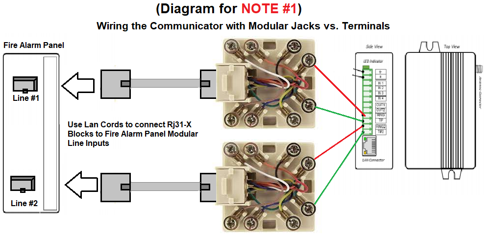
NOTE #1: In some cases the output terminals for Line #1 and Line #2 are actually plug in jacks. If this is the case, you will need to connect Line #1 and Line #2 to the Communicator using the provided Phone jack harness. (See “Harness Wiring the Communicator” diagram below.)
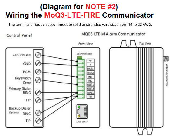
NOTE #2: If your COMMUNICATOR is a model MOQ3-LTE-FIRE, You will not have two sets of telco ring & tip input terminals. You will be required to run a “parallel set of wires” from the single TIP & RING to BOTH sets of Line #1 and Line #2 to allow BOTH lines to be connected to the Communicator at the same time. (See “Parallel” Wiring” Diagram Below)
(5) Connect the antenna after running it through the a pre-cut hole in the FAP to allow the antenna to be exposed outside the FAP.
(6) If you had the IP/LAN portion of the communicator activated, then you need connect a LAN cord into the “LAN Connector” located under the terminals of the Communicator. The other side of the LAN / network cord should be plugged directly into either a local router or switch.
(7) Wait a full 15 minutes, to allow the communicator to power up, self register itself and upload any possible new firmware before moving forward with the next step.
(8) After 15 minutes, our FAP is ready to test into the Emergency Alarm Center.
(9) Call the Emergency Monitoring Center at 1-800-365-2527. When a Live operator answers, Tell them your installing and testing your Fire alarm, and provide them with your account number (See above) and password. (“Welcome“ – unless you have already updated it.) Tell them to put the account on test for 1 hour.
(10) Locate the Backup battery for your FIRE ALARM PANEL.
(11) Disconnect ONE SIDE of the battery lead.
(12) Wait until the Trouble alarm is shown on the Fire Alarm Panel for either LOW BATTERY or MISSING BATTERY.
Note: Do not reconnect the battery yet…
(13) Allow the alarm to stay in trouble alarm condition for 5 full minutes, then reconnect the battery lead and the trouble alarm should stop.
(14) Call the Emergency Monitoring Center again at 1-800-765-2580. When a live alarm operator answers, tell them that you have just completed testing of your alarm system and you would like to confirm what signals were received.
(15) The operator should confirm receipt of the alarm signal(s) to you. (NOTE: If they could not locate any signals from your Alarm Panel, you will need to contact Technical Support as soon as possible at 1-888-769-8977.)
(16) Once the Live Operator has verified that your alarm system has sent in a signal. you can continue to test multiple zones and areas of the alarm by arming the alarm system and then causing it to go into alarm either by tripping pull stations or smoke detectors. Remember to allow the alarm to sound for 2 minutes each time.
(17) When your done testing multiple zones, call the monitoring center again to confirm signals were received for those other areas as well.
(18) Your now fully competed with your Fire Alarm Monitoring. Please complete the form below:
Fill out my online form.